Networking Tutorial by Ben Eater
Summary: The networking tutorial youtube series by Ben Eater is tremendous. It consists of 13 short youtube videos each explaining a bite-sized computer networking concept.
Ben Eater, who focuses on explaining CS fundamentals, does an excellent job explaining networking from first principles. The tutorial shows real world examples where Ben shows the electrical signals from actual wires to demostrate how data is sent along a network.
For a quick intro to the core basics of networking, I would say this is a fantastic way to get an 80/20 understanding of the topic.
You can find the playlist of the tutorial here.
Rating: 9.5/10
Videos
- Sending digital information over a wire
- Intro to fiber optics and RF encoding
- Clock synchronization and Manchester coding
- Analyzing actual Ethernet encoding
- The importance of framing
- Frame formats
- Lower Layers of the OSI Model
- The Internet Protocol
- ARP: Mapping Between IP and Ethernet
- Looking at ARP and Ping Packets
- Hop by Hop Routing
- TCP: Transmission Control Protocol
- TCP Connection Walkthrough
1. A Tour of Computer Systems
- Connect a voltage to the wire and vary it between 0V and 5V.
- The states (0V and 5V) are called symbols. They are used to represent symbols: 0V represents 0, 5V represents 1. This is binary.
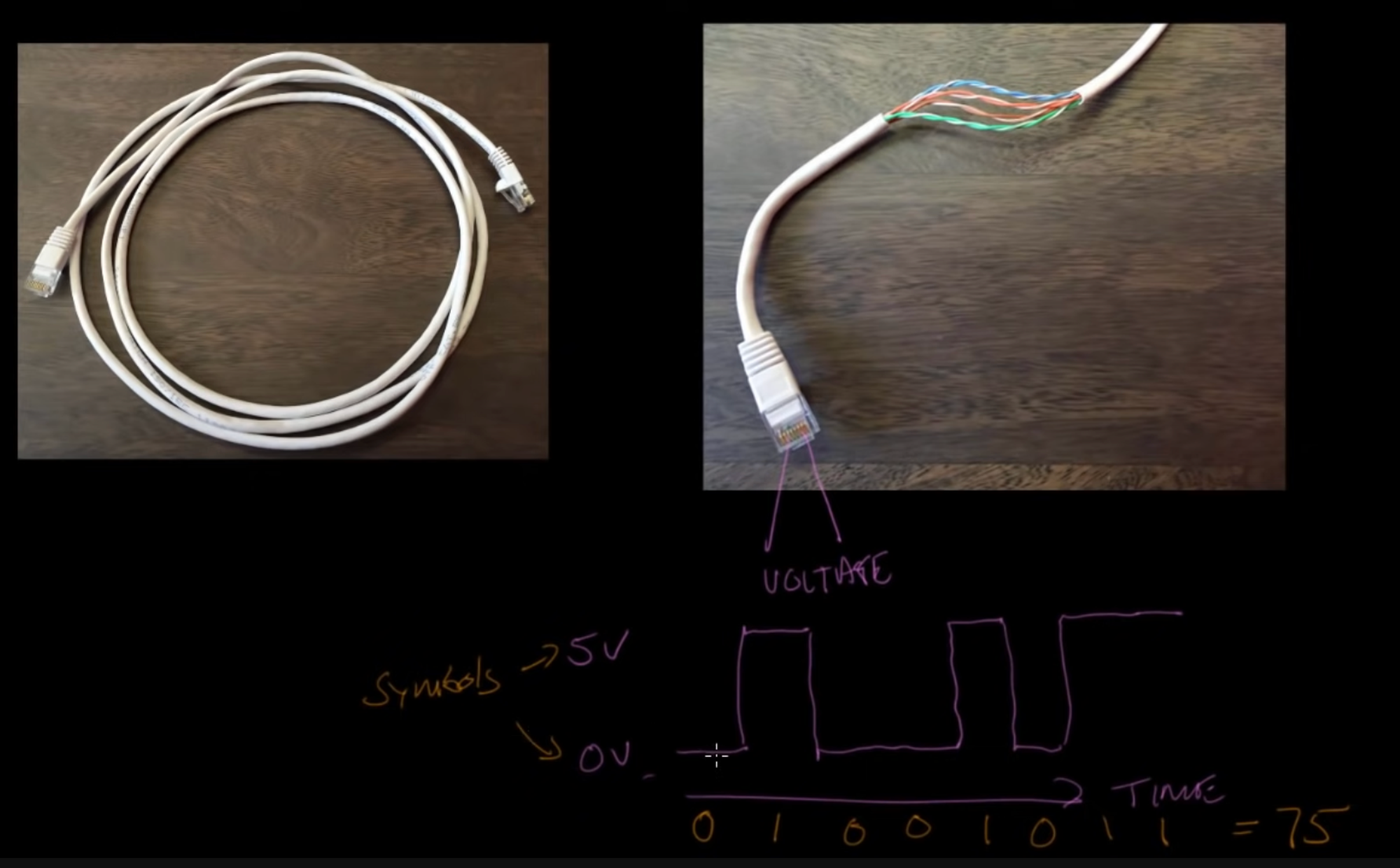
- In the above example, the pattern generated is 01001011, which is the number 75
- In this case, the symbol rate is 1 symbol per second. The symbol rate (symbols/second) can also be called baud. 10 symbols/sec = 10 baud.
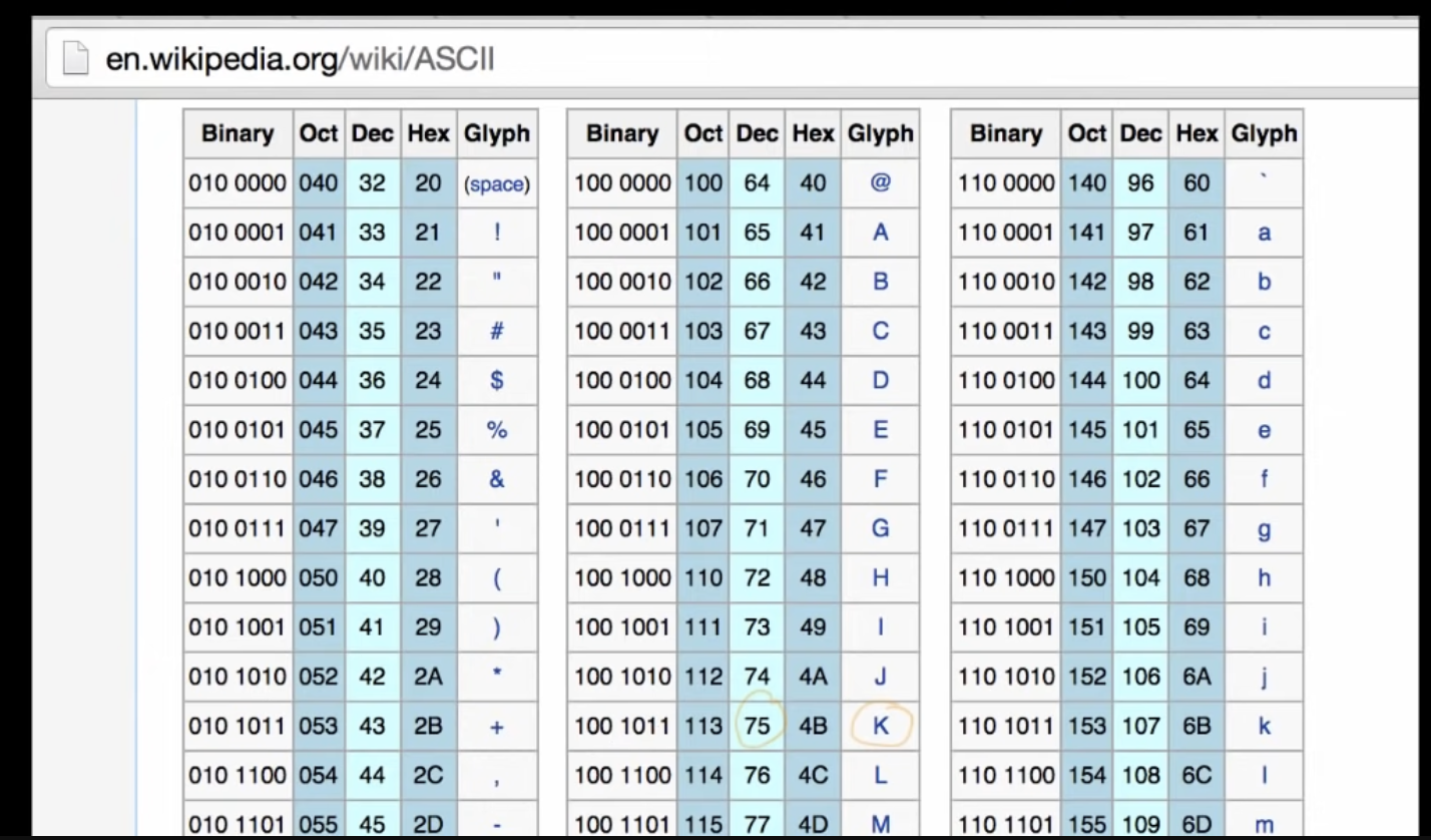
- You can send anything you want, so long as you agree on the mapping between binary digits and data. ASCII is an example, where different binary digits map to different symbols.
2. Intro to fiber optics and RF encoding
- Fiber cable tends to have fiber strand on the outside with cladding on the inside.
- There is a difference in the refractive index, so the light will refract through and can go through the cable even if it’s bent.
- Similar to the electric signals in the cables in video 1, we can send info via having light off (0) or light on (1).
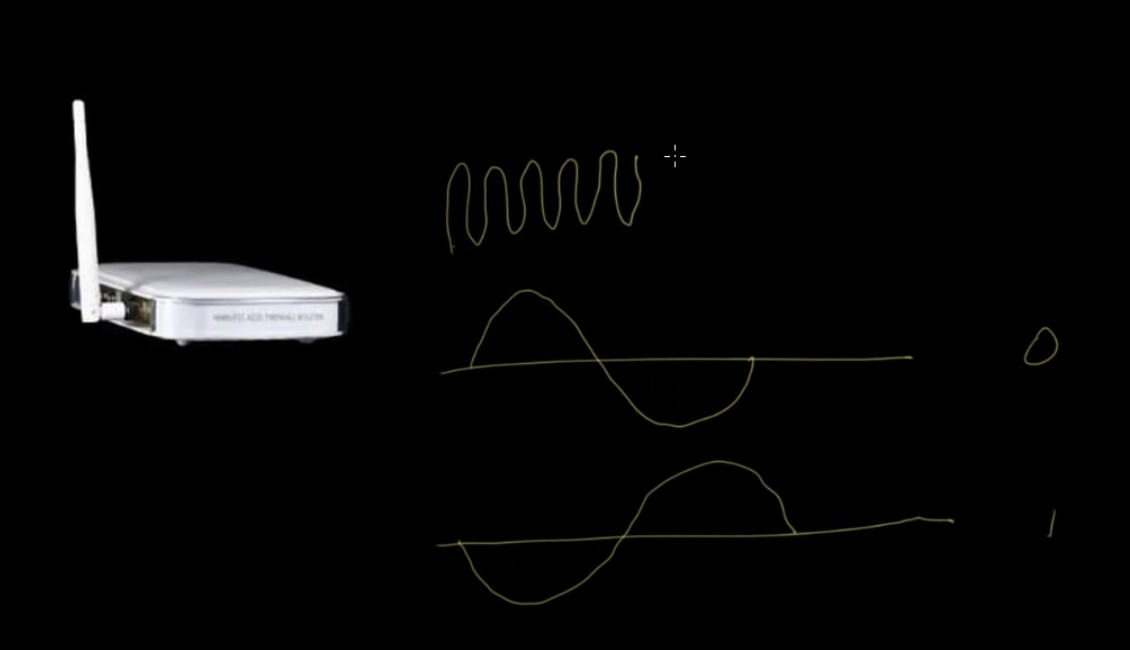
- In a wireless system, you can vary the voltage coming out of the antenna’s radio waves. A receiver would then amplify them and convert the signal to binary.
3. Clock synchronization and Manchester coding
- Imagine that you have two computers with a cable connecting them, which is sending electrical impulses.
- In order to know exactly how many zeros/ones are sent, you need to have a synchronized clock.
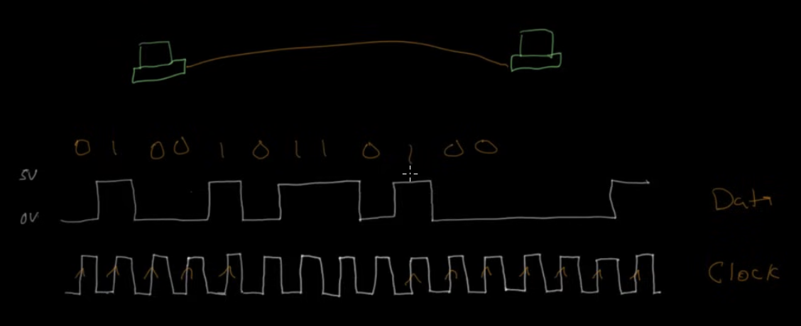
- You can add a clock that is doing a transition from 0 to 1 at a given interval. Both sides of the link must agree on that same clock rate.
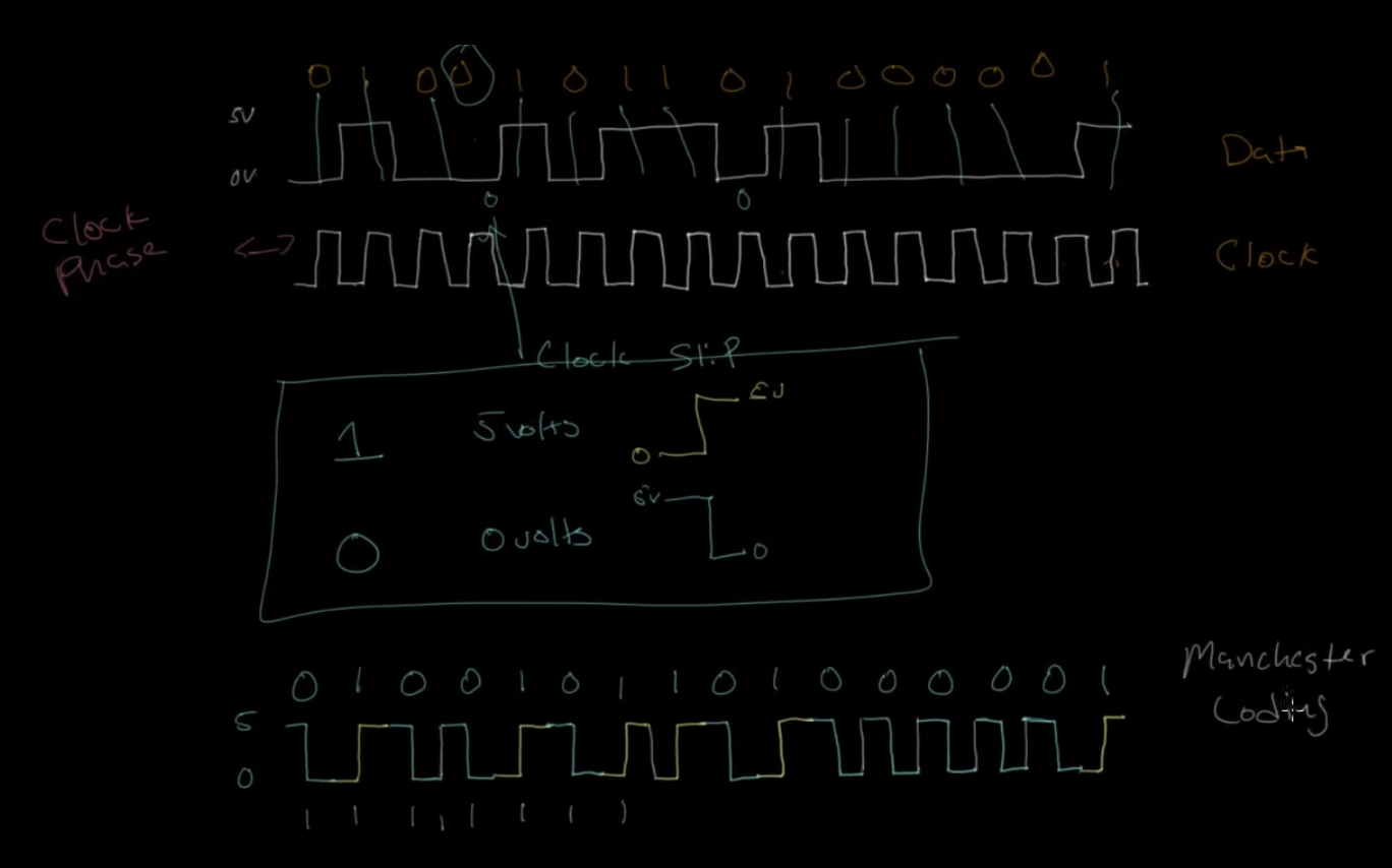
- Clock slip is when we are missing a bit. We would then know that the data we are receiving is not going to make sense.
- One way to make sure that both clocks are in sync would be using a GPS antenna’s clock and synchronize the clocks to that.
- Another solution is to have an atomic clock in the computer itself. This is fairly uncommon.
- Another approach is to send a separate signal. You send both the data and the clock. The receiving computer doesn’t use its own clock, but the clock of the sender. One issue is that the clock and data need to line up. It is possible for the network link to be faster for one or the other of the clock vs. the data.
- Finally, you can combine the clock and the data by using different symbols to represent 0’s and 1’s. Traditionally, you might use 5V to send a 1 and 0V to send a 0. Or more specifically, a 1 would be a transition from 0V to 5V and a 0 would be a transition from 5V to 0V.
-
Even if the data is repeating (e.g. 0, 0) - there is still a transition you would just go to 5V and then right back to 0V and the signal would change phase twice as quickly. This makes it easy to follow along, and the clock doesn’t need to be completely perfect. It just needs to distinguish between when we shift from a 0 to a 1 or vice versa vs. when we repeat 1 or repeat 0.
-
This method is called Manchester coding.
4. Analyzing actual Ethernet encoding
- 4 pairs of wires within ethernet cable
- 10 BASE-T is a standard developed by IEEE → allows you to transmit data at 10Mbps. There are other standards, but this one is used because it is easier to understand for the demo
- Voltage transitions come in every 100ns (10^-7 s)
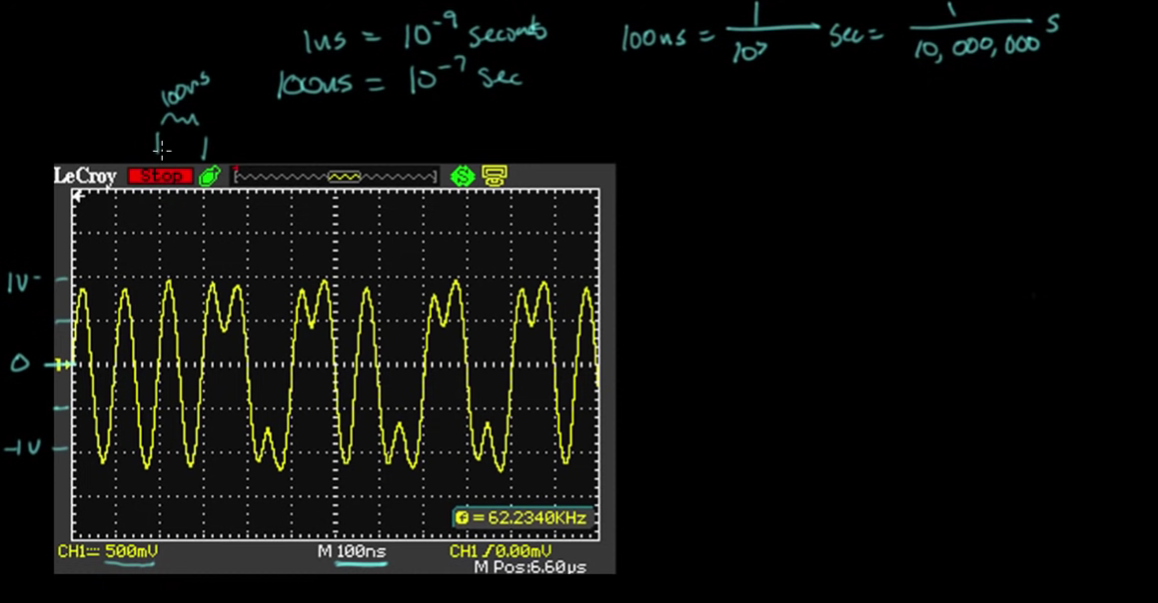
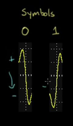
- Going positive to negative represents a 0, neg to pos is a 1
- Also worth noting that the bits are often flipped (little endian vs. big endian)
5. The importance of framing
- How does the computer know which group of bits go in which order?
- HDLC: High Level Data Link Control
- HDLC uses a special bit pattern called a frame delimiter or a flag, which is 01111110. This pattern of bits indicates that the next bit is where to start interpreting
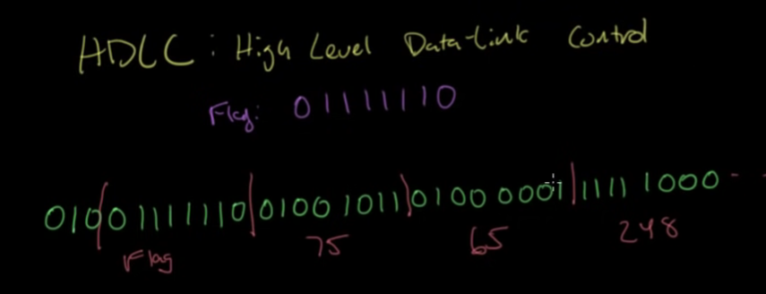
- How do you ensure that a flag doesn’t accidentally get picked up, when it’s not intended?
- If 5 bits happen to show up in a row, the next one should be a 0. The 0 will then be ignored. This is called bit stuffing.
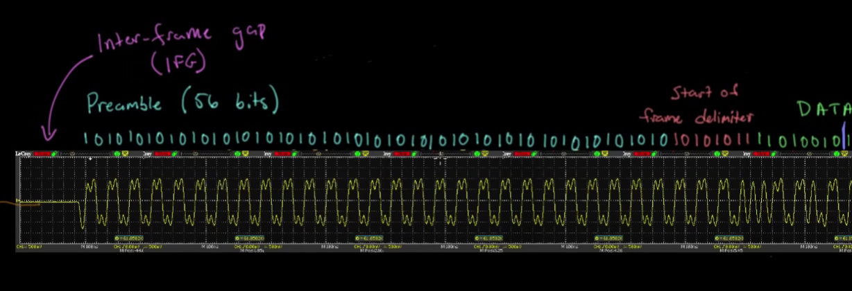
- In order to ensure that the clocks can be synchronized, the beginning of the pattern generally starts with 56 straight bits that alternate 101010 etc. Then the frame delimiter is shown.
6. Frame formats
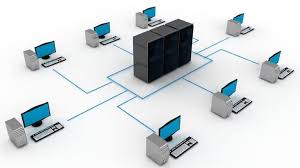
- Point to point data link: Two computers are directly connected. In practice, this is more rare.
- Multipoint/broadcast data link: many computers can be connected.
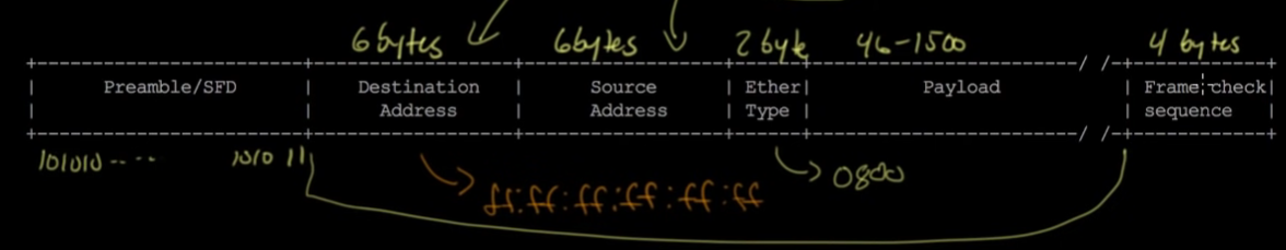
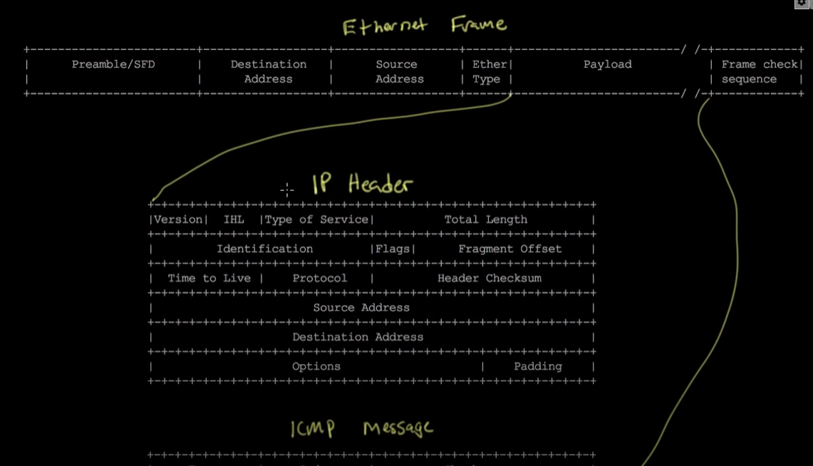
- As shown below, the bits/bytes sent are in the following order - Preamble and Frame Delimiter, Destination Address, Source Address, Ether Type, Payload, then Frame Check Sequence (to verify that all frames were sent appropriately)
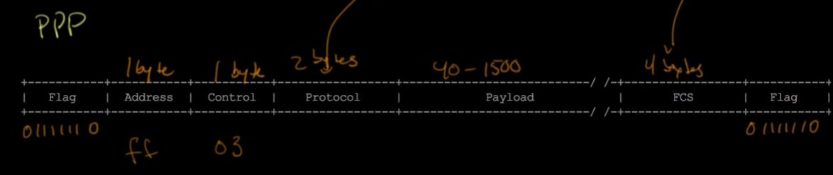
- PPP (point to point) does things in a different order:
7. Lower Layers of the OSI Model
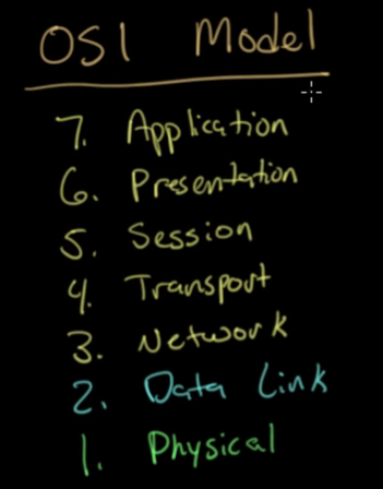
- Layer 1 and 2 technologies:
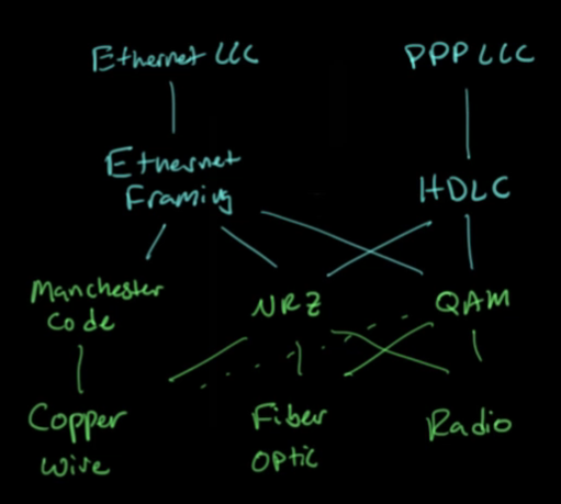
- Each layer depends on the layer(s) below it
8. The Internet Protocol
- If you want to send a network request from host A to host B, your host will have no knowledge of host B’s MAC address.
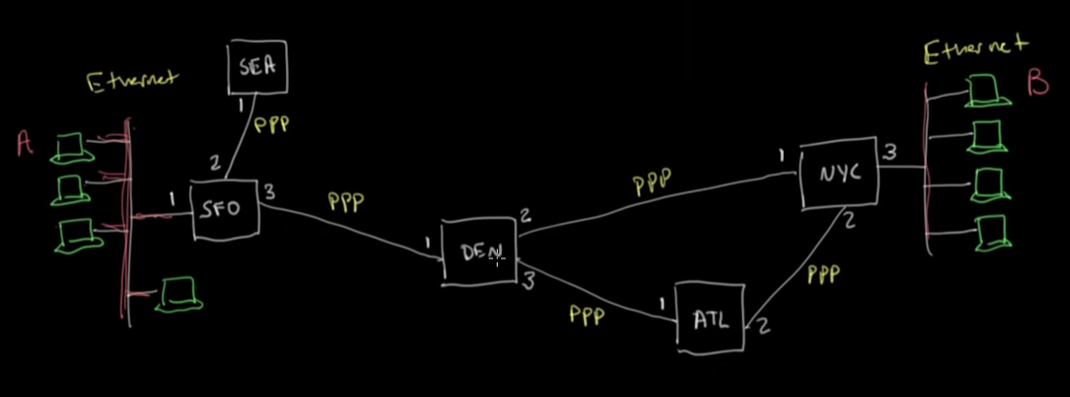
- In the above diagram, if it’s going from SFO to NYC, while it doesn’t initially know the entire route, at each step, the machine is aware of what machine to forward to next.
- Ranges of IP addresses are grouped together by prefix and each node knows which node to forward to for each given range.
9. ARP: Mapping Between IP and Ethernet
- Subnet mask says the number of bits that are matched on the ethernet network in their prefix
- The router is configured in order to say, if it doesn’t match that prefix, it is not on the local network, so send the packet to the router to be forwarded
- ARP = address resolution protocol
- The sending host is finding a way to get the hardware address of the target using the protocol address of the target. Matching protocol address host will respond with its hardware address.
10. Looking at ARP and Ping Packets
- The “ping” command lets you send an IP packet to another IP address and get a reply back
- Wireshark will show you specific details of the network requests that are occurring
- You can see the hex/bytes of different requests
11. Hop by Hop Routing
- The time to loop field ensures that the packet does not loop around infinitely looking for a home. It will drop or make a decision if it finds itself looping consistently
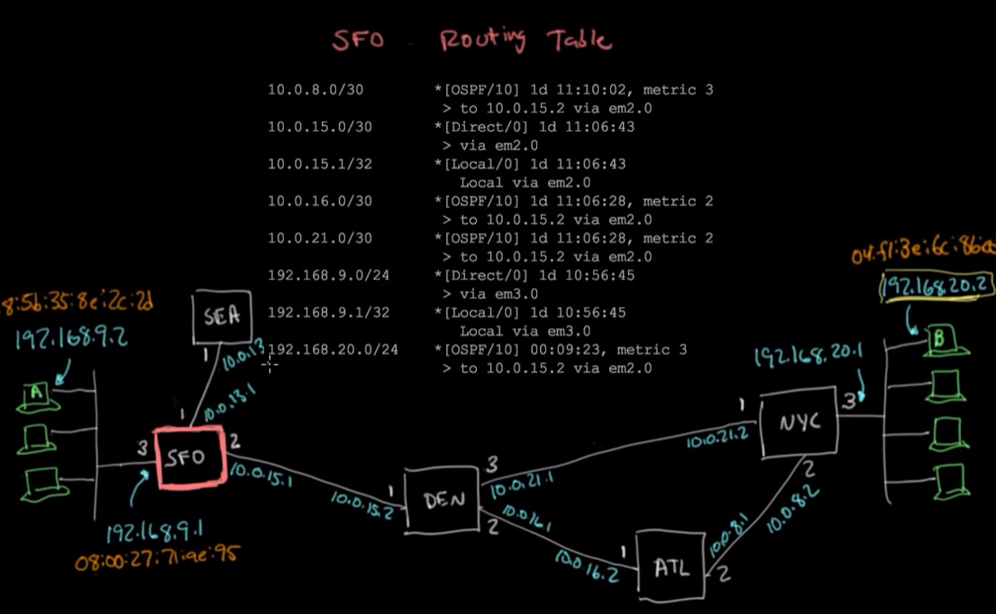
- At each node, the routing table will be used to identify the best route by analyzing the prefix of the destination.
12. TCP: Transmission Control Protocol
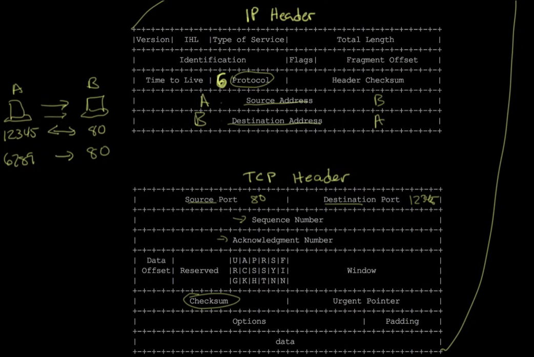
- IP packet has to fit inside a frame, which is limited to about 1500 bytes of payload. If you want to send more data, it has to be split into multiple packets.
- When you split data into multiple packets, it’s possible to lose packets. So we want to be able to detect loss and retransmit.
- It’s also possible for packets to arrive out of order. So we need a strategy for reordering.
- You also want to be able to handle multiple conversations.
- And finally, you want some form of flow control. If packets are being dropped, it’s important to slow down the flow of data.
- TCP solves the above problems. It sets up a byte stream service. It is connection oriented and reliable.
- SYN/ACK → synchronize (a desire to establish a connection) and acknowledge
- Sequence number is kept track of in order to be able to reorder if necessary
13. TCP Connection Walkthrough
- The device that is initiating the connection is called the client and the device that it’s speaking with is called the server. The connection is bidirectional, so after being established, it doesn’t really matter what device established the connection.
- At the beginning of the connection, the client sends the first packet which has a SYN (synchronize) bit and sequence number 0. The server responds with ACK (acknowledge) and sequence number 1, plus it sends a SYN bit with sequence 0. Then the client sends ack 1, syn 1. After those 3 packets are sent, the connection is established.
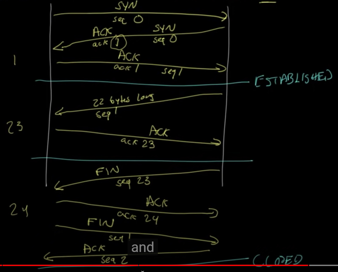
- In wireshark, you can see the syn and ack numbers, plus all other relevant data.